
The Advantages and Disadvantages of Via in Pad
Disadvantages of Via in Pad
As components continue to shrink in size and hardware engineers are tasked with making smaller devices, they have to utilize new techniques to implement them properly. One of these techniques is via in pad. Via in pad is a process that places a via directly in the copper landing pads of the component. This allows for a smaller component fan out and reduced circuit board size. There are several things that should be considered before using this technique, however. Having an understanding of the pros and cons is essential for proper implementation.
The main reason to use via in pad is for small component pitch devices such as fine pitch BGAs or SMDs. These devices have very small landing pads and there is no room to place a traditional via underneath them. As a result, it is necessary to route them with capped via in pad to avoid solder wicking and coplanarity issues.
In addition, for high-speed designs, via in pad is also used to help with heat dissipation and maintaining the components temperature. Oftentimes, this method is recommended by the device manufacturer.
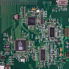
The Advantages and Disadvantages of Via in Pad
One of the advantages to using via in pad is that it can improve signal integrity by reducing the distance of the signal path to ground. This can be a critical factor in high-speed and high-density design. Additionally, it can be beneficial for reducing inductance due to the decreased distance of the signal path.
The downside to this technique is that it can increase the cost of the PCB due to added steps in the manufacturing process. First, the copper pads must be plated with nickel to prevent solder wicking into the holes. Then, the vias must be filled with a non-conductive epoxy, cured, planarized, and then capped. Additionally, a conductive epoxy is sometimes used in place of the non-conductive one for additional heat dissipation.
Another disadvantage is that using via in pad requires the creation of an extra manufacturing file to be used with the standard excellon drill file. This can make the job more complicated for contract PCBA manufacturers. This can lead to delays in production and higher costs.
Overall, there are many benefits to using via in pad, including improved signal integrity and reduced inductance. It is important to understand all the aspects of via in pad before implementing it on a project, however. Whether or not it is the right solution for your design depends on a variety of factors, including the device manufacturer’s recommendations, DFM/DFA checks, and manufacturing costs. Contact our engineering team for more information if you are considering using this technology on your next project. We can discuss the specifics of your design and help you decide if it is an optimal choice. Our expert engineers can even recommend alternative methods that may be more suitable for your application. You can reach us online or by phone. We look forward to hearing from you!